Encoders in Verilog
The encoder works just as the opposite of the decoder. Its function is to encode a given input and provide encoded output. In general, an encoder has at most 2N inputs and N outputs. Let’s focus on the four-to-two encoder with the truth table presented.

The output of the encoder is the binary representation of the input. While constructing the truth table, we assumed that no two inputs will have logic level 1 at the same time. If such a case occurs, then the output of the decoder becomes unpredictable.
To overcome this problem, we can add priority to inputs such that the output is the one with the higher precedence.
Octal to Binary Encoder
Octal to binary Encoder has eight inputs, Y7 to Y0 and three outputs A2, A1 & A0. Octal to binary encoder is nothing but 8 to 3 encoder. The block diagram of octal to binary Encoder is shown in the following figure.
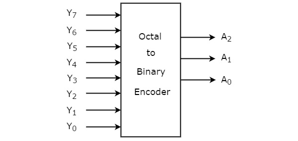
At any time, only one of these eight inputs can be ‘1’ in order to get the respective binary code. The Truth table of octal to binary encoder is shown below.
| Inputs | Outputs | |||||||||
|---|---|---|---|---|---|---|---|---|---|---|
| Y7 | Y6 | Y5 | Y4 | Y3 | Y2 | Y1 | Y0 | A2 | A1 | A0 |
| 0 | 0 | 0 | 0 | 0 | 0 | 0 | 1 | 0 | 0 | 0 |
| 0 | 0 | 0 | 0 | 0 | 0 | 1 | 0 | 0 | 0 | 1 |
| 0 | 0 | 0 | 0 | 0 | 1 | 0 | 0 | 0 | 1 | 0 |
| 0 | 0 | 0 | 0 | 1 | 0 | 0 | 0 | 0 | 1 | 1 |
| 0 | 0 | 0 | 1 | 0 | 0 | 0 | 0 | 1 | 0 | 0 |
| 0 | 0 | 1 | 0 | 0 | 0 | 0 | 0 | 1 | 0 | 1 |
| 0 | 1 | 0 | 0 | 0 | 0 | 0 | 0 | 1 | 1 | 0 |
| 1 | 0 | 0 | 0 | 0 | 0 | 0 | 0 | 1 | 1 | 1 |
From Truth table, we can write the Boolean functions for each output as
We can implement the above Boolean functions by using four input OR gates. The circuit diagram of octal to binary encoder is shown in the following figure.
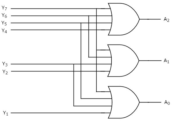
The above circuit diagram contains three 4-input OR gates. These OR gates encode the eight inputs with three bits.
Drawbacks of Encoder
Following are the drawbacks of normal encoder.
There is an ambiguity, when all outputs of encoder are equal to zero. Because, it could be the code corresponding to the inputs, when only least significant input is one or when all inputs are zero.
If more than one input is active High, then the encoder produces an output, which may not be the correct code. For example, if both Y3 and Y6 are ‘1’, then the encoder produces 111 at the output. This is neither equivalent code corresponding to Y3, when it is ‘1’ nor the equivalent code corresponding to Y6, when it is ‘1’.
So, to overcome these difficulties, we should assign priorities to each input of encoder. Then, the output of encoder will be the code corresponding to the active High input, which has higher priority. This encoder is called as priority encoder.
Priority Encoder
Within the priority encoder, we still assume that all inputs will not be zero at the same time. To check whether such an input comes, we can add a valid signal, v, to the output. This will indicate that the obtained output is either valid or not. Here don’t care conditions are represented by “ - “ sign.

we can construct the combinational circuit of the four-to-two priority encoder as follows:
A 4 to 2 priority encoder has four inputs X3, X2, X1 & X0 and two outputs A1 & A0. Here, the input, X3 has the highest priority, whereas the input, Y0 has the lowest priority.
In this case, even if more than one input is ‘1’ at the same time, the output will be the binary code corresponding to the input, which is having higher priority.
We considered one more output, V in order to know, whether the code available at outputs is valid or not.
If at least one input of the encoder is ‘1’, then the code available at outputs is a valid one. In this case, the output, V will be equal to 1.
If all the inputs of encoder are ‘0’, then the code available at outputs is not a valid one. In this case, the output, V will be equal to 0.
Use 4 variable K-maps for getting simplified expressions for each output.

The simplified Boolean functions are

We can implement the above Boolean functions using logic gates. The circuit diagram of 4 to 2 priority encoder is shown in the following figure.


Verilog Description of Four-to-Two Priority Encoder


No comments:
Post a Comment