NOT GATE
one of the basic logic gate having only a single input and a single output. It is also known as inverter or inverting buffer. When the input signal is "low" the output signal is "high" and vice-versa.

AND GATE: is used to perform logical multiplication of binary input. The Output state of the AND gate will be high (1) if both the input is high (1), else the output state will be low(0) if any of the input is low (0).
The Boolean Expression or logic for the AND gate is the logical multiplication of inputs denoted by a full stop or single dot as :
The value of X will be True when both the inputs will be True

OR GATE
The output state of OR gate will be high i.e., (1) if any of the input state is high or 1, else output state will be low i.e., 0.
The Boolean Expression for the OR gate is the logical addition of inputs denoted by plus sign (+) as
The value of X will be high(true) when one of the inputs is set to high (true).

NOR GATE
The NOR gate is the type of universal logic gate. It takes two or more inputs and gives only one output. The output state of the NOR gate will be high (1) when all the inputs are low (0). NOR gate returns the complement result of the OR gate. It is basically a combination of two basic logic gates i.e., OR gate and NOT gate.

NAND GATE
The NAND Gate is another type of Universal logic gate. The NAND gate or "Not AND" is the combination of two basic logic gates AND gate and the NOT gate connected in series. It takes two or more inputs and gives only one output. The output of the NAND gate will give result high (1) when either of its input is high (1) or both of its input are low (0). In simple, it performs the inverted operation of AND gate.
The Boolean Expression of NAND Gate is as follows:X = (A. B)’

XOR GATE
The XOR gate is a special logic gate used to perform modulo-2 addition. It has two inputs and one output. The output is HIGH (1) only when the inputs are different; otherwise, it is LOW (0). XOR gates are widely used in arithmetic logic circuits, comparators, and error detection systems.
The Boolean expression of XOR Gate is:
X = A’B + AB’ OR X=A XOR B or X=(A ⊕ B)

XNOR GATE
The XNOR is the combination of XOR gate and NOT gate. The output of the XNOR gate is high(1) when both the inputs are high (1) or low(0). In other words, the output of the XNOR gate is high(1) when both the inputs are the same. the XNOR gate can sometimes be called as Equivalence gate. In simple words, The XNOR gate is the complement of the XOR gate.
The following is the Boolean expression of the XNOR gate,
Y = A ⊙ B or Y = AB + A’B’ or Y = (A ⊕ B)’

binary number TO decimal
(101101.101)₂ = 1·2⁵+1·2³+1·2²+1·2⁰+1·2⁻¹+1·2⁻³
=32+8+4+1+0.5+0.125=45.625₁₀
binary number to Hexa decimal
0010 1101 . 1010₂ = 2D.A₁₆
Answer: (45.625)₁₀ = (2D.A)₁₆

(i) F=AB+A(B+C)+B'(B+D)
F=AB+AB+AC+B'B+B'D
=AB+AC+B'D
apply complement on both side
F'= (AB+AC+B'D)' (use demorgan law)
=(AB)' . (AC)' . (B'D)'
=(A'+B')(A'+C')(B+D)
(ii) F=A+B+A'B'C
=A+B+(A'B'C) (use demorgan law)
apply complement on both side
F'=( A+B+(A'B'C) )'
F'=A' B' (A'B'C)'
F'=A' B' (A''+B''+C')
F'=A' B' (A +B +C')
F'=A'B'C'
CANONICAL FORM OR STANDAND FORM,IT HAS 2 FORMS
1 CANONICAL SOP OR STANDARD SOP
2 CANONICAL POS OR STANDARD POS
CANONICAL SOP ALL THE PRODUCT TERM WHICH ARE CALLED AS min trems (m)
CANONICAL POS ALL THE SUM TERMS WHICH ARE CALLED AS MAX TERMS (M)
MIN TERM( m): It Is PRODUCT Term conatins all 'N' Varible either In Complimented Or Uncomplimented form
MAX TERMS(M): it is SUM terms which contains 'N' variables either in complimented or uncomplimented form

FIND CANONICAL SOP Y(A,B,C)=∑m(0,1,2,7)
Y=m0+m1+m2+m7
Y=A'B'C'+A'B'C+A'BC'+ABC ,
FIND CANONICAL POS Y=πM(3,4,5,6)
Y=M3.M4.M5.M6
Y=(A+B'+C')(A'+B+C)(A'+B+C')(A'+B'+C)


12. Determine and analyze the value of the base (x) for the following number-system equations: a) (211)x =(152)8 b) (292)10 = (1204)x
(a) (211)x=(152)₈
converting LHS & RHS to the decimal system
2*x²+1*x^1 +1* x^0=1* 8^2 + 5 * 8^1 + 2 * 8^0
2x²+x+1=1*64 + 5*8 + 2
⇒ 2x²+x−105=0
⇒ 2x2+x−105=0
Factorize:
Therefore x=7 or x=−7.5
since base can't be a negative number x=7
(b) (292)₁₀=(1204)x
x³+2x²+4=292.
find the cube root solution
or
try for differnt values of x=0,1,2,3,4,5,6 verify LHS & RHS are equal
For x=6: 216+72+4=292.
Therefore x=6.
Binary product (1011)₂* (1110)₂
1011
× 1110
-------
0000
1011
1011
1011
-------
10011010₂
Converting the binary result to the decimal system
10011010₂=154₁₀. ---------------------------------------(1)
Converting binary to decimal
1011₂=11₁₀, 1110₂=14₁₀,
Multiplication in decimal: 11×14=154₁₀.---------------------------------------(2)
eqn (1) and (2) are equal . Verified.


- f(w,x,y,z)=prod M(0,1,2,3,4,5,7,8,9)


Weight sum = 6+3+1−1=9.
Complementing all bits changes the weighted value to 9−N. Therefore a valid 6,3,1,−1 decimal code is self-complementing: the complement of the code for digit N represents 9−N
|
Decimal Digit |
Code 631-1 |
|
0 |
0000 |
|
1 |
0001 |
|
2 |
0011 |
|
3 |
0100 |
|
4 |
0101 |
|
5 |
0111 |
|
6 |
1000 |
|
7 |
1010 |
|
8 |
1011 |
|
9 |
1111 |
CA₁₆=202₁₀; E8₁₆=232₁₀
Multiplication in decimal : 202×232 = 46864₁₀ ----------(1)
Multiplication hexa Decimal system:
CA
× E8
-----
640
A1E
----
B710₁₆
converting result hexa decimal to decimal system
B710₁₆ =11* 16^3 +7*16^2 + 1*16^1 + 0* 16^0
B710₁₆ =11*4096 +7*256 + 1*16 = 46864₁₀. ------------------(2)
hence result in decimal system eqn (1) & hexa decimal system (2) are same Verified.


2. Design and develop a BCD-to-Excess-3 code converter using the K-map method and construct its complete logic circuit.
- For Output E3:
- Minterms: ∑𝑚(5, 6, 7, 8, 9) + Don't cares ∑𝑚 d(10, 11, 12, 13, 14, 15)
- For Output E2:
- Minterms: ∑𝑚(1,2,3,4, 9) + Don't cares ∑𝑚 d(10, 11, 12, 13, 14, 15)
- For Output E1:
- Minterms: ∑𝑚(0, 3, 4, 7, 8) + Don't cares ∑𝑚 d(10, 11, 12, 13, 14, 15)
- For Output E1:
- Minterms: ∑𝑚(0, 2, 4, 6, 8) + Don't cares ∑𝑚 d(10, 11, 12, 13, 14, 15)


7. Analyze the given logic circuit using K-map or Boolean algebra, derive and simplify the expressions for G1, G2, G3, G4, G5, G6 and X, and redraw the simplified circuit ?

ANALYSIS OF LOGIC CIRCUIT
Step 1: Identify the outputs of individual gates
From the circuit:
Input Inverters : C → C′ , B→B′
Gate G1
G1 is a NAND gate with inputs and .
Using De Morgan's theorem: Out Put of G1=D′+C
Gate G2
G2 is an AND gate with inputs and . Out Put of G2=C′B′
Gate G3
G3 is an OR gate with inputs and . Out Put is G3=A+B′
Gate G4
G4 is a NOR gate with inputs and .
Using De Morgan's theorem: Out Put of G4=A′B′
Gate G5
G5 is a NOR gate with inputs and .
Substituting:
Using De Morgan's theorem:
Now,
Therefore,
Expanding:
Since, C′C=0
Therefore, G5=DBC′
Gate G6
G6 is a NAND gate.
Substituting:
We know:
Therefore,
Simplifying inside:
Therefore,
Using De Morgan's theorem: G6=A+B
Final Output X
The final gate is an OR gate.
Substituting:
Using the absorption theorem:
Therefore,
Hence,
X=A+B


ANALYSIS OF LOGIC CIRCUIT
Gate X1
From the diagram, is a NOR gate whose two inputs are connected to .
Therefore:
Since:
Therefore: X1=D′
Gate X2
is a NAND gate with inputs and .
Using De Morgan's theorem: X2 =A′+B′
Gate X3
is a 3-input AND gate.
Its inputs are: B , C, X1
Therefore:
Since:
Therefore:
X3=BCD′
Gate X4
is an OR gate.
Substituting:
Using:
Therefore:
X4=A′+B′+BCD′
Final Output F
The final gate is an OR gate with inputs and .
Substituting:
Rearranging:
Using the identity:
D+D′BC=D+BC
Therefore:
Now,
Therefore:
F=A′+B′+C+D


|
Decimal Equivalent |
Gray Code Inputs (G3G2G1G0) |
Binary Outputs (B3B2B1B0) |
|
0 |
0000 |
0000 |
|
1 |
0001 |
0001 |
|
2 |
0010 |
0011 |
|
3 |
0011 |
0010 |
|
4 |
0100 |
0111 |
|
5 |
0101 |
0110 |
|
6 |
0110 |
0100 |
|
7 |
0111 |
0101 |
|
8 |
1000 |
1111 |
|
9 |
1001 |
1110 |
|
10 |
1010 |
1100 |
|
11 |
1011 |
1101 |
|
12 |
1100 |
1000 |
|
13 |
1101 |
1001 |
|
14 |
1110 |
1011 |
|
15 |
1111 |
1010 |
- For Output (B3):
- Minterms: B3=∑𝑚(8, 9, 10, 11, 12, 13, 14, 15)
- For Output (B2):
- Minterms: B2=∑𝑚(4, 5, 6, 7, 8, 9, 10, 11)
- For Output (B1):
- Minterms: B1=∑𝑚(2, 3, 4, 5, 8, 9, 14, 15)
- For Output (B0):
- Minterms: B0=∑𝑚(1, 2, 4, 7, 8, 11, 13, 14)
- Draw the K-Map for each output and simplfy, then draw logic circuit
Karnaugh Map (K-Map) is a graphical method used to simplify Boolean expressions without using lengthy Boolean algebra. It helps reduce the number of logic gates by grouping adjacent cells in a truth table, making digital circuits simpler and more efficient.
- K-map can be used for SOP and POS forms.
- It organizes truth table values into a grid for easy simplification.
Depending on the required representation, a K-Map is filled with 1s (for SOP) or 0s (for POS), and adjacent cells are grouped to obtain a simplified Boolean expression.
A half adder is a basic combinational circuit that adds two single-bit binary inputs (A and B) to produce a SUM using an XOR gate and a CARRY using an AND gate, without considering any carry-in from a previous stage.
- Performs binary addition of two single-bit inputs, generating a SUM (A ⊕ B) and CARRY (A · B).
- Cannot handle carry-in from a previous stage, making it suitable only for the first stage of multi-bit addition.
Truth Table of Half Adder
A B Sum Carry 0 0 0 0 0 1 1 0 1 0 1 0 1 1 0 1

A Half Subtractor is a combinational logic circuit that performs the subtraction of two single-bit binary numbers. It has two inputs (A and B) and produces two outputs: Difference and Borrow.
- Can be implemented using a combination of XOR, AND, and NOT logic gates.
- Acts as the basic building block for designing full subtractors and multi-bit subtraction circuits.
Truth Table of Half Subtractor
A B Diff Borrow 0 0 0 0 0 1 1 1 1 0 1 0 1 1 0 0

| Feature | Prime Implicant (PI) | Essential Prime Implicant (EPI) |
|---|---|---|
| Definition | The largest possible valid group of adjacent ones. | A PI that covers at least one unique 1- cell not covered by any other PI. |
| In Final Solution | May or may not appear in the final simplified expression. | Always appears in the final simplified expression. |
| Uniqueness | Can overlap with other groups entirely. | Contains a distinguished cell unique to it. |
Carry Look-ahead Adder :
A carry look-ahead adder reduces the propagation delay by introducing more complex hardware. In this design, the ripple carry design is suitably transformed such that the carry logic over fixed groups of bits of the adder is reduced to two-level logic. Let us discuss the design in detail.
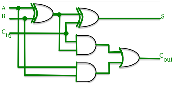

Consider the full adder circuit shown above with corresponding truth table. We define two variables as 'carry generate' and 'carry propagate' then,
The sum output and carry output can be expressed in terms of carry generate and carry propagate as
where produces the carry when both , are 1 regardless of the input carry. is associated with the propagation of carry from to .
The carry output Boolean function of each stage in a 4 stage carry look-ahead adder can be expressed as
From the above Boolean equations we can observe that does not have to wait for and to propagate but actually is propagated at the same time as and . Since the Boolean expression for each carry output is the sum of products so these can be implemented with one level of AND gates followed by an OR gate.
The implementation of three Boolean functions for each carry output (, and ) for a carry look-ahead carry generator shown in below figure.

The adder produce carry propagation delay while performing other arithmetic operations like multiplication and divisions as it uses several additions or subtraction steps. This is a major problem for the adder and hence improving the speed of addition will improve the speed of all other arithmetic operations. Hence reducing the carry propagation delay of adders is of great importance. There are different logic design approaches that have been employed to overcome the carry propagation problem. One widely used approach is to employ a carry look-ahead which solves this problem by calculating the carry signals in advance, based on the input signals. This type of adder circuit is called a carry look-ahead adder.
Here a carry signal will be generated in two cases:
- Input bits A and B are 1
- When one of the two bits is 1 and the carry-in is 1.

The propagation time is equal to the propagation delay of each adder block, multiplied by the number of adder blocks in the circuit. For example, if each full adder stage has a propagation delay of 20 nanoseconds, then will reach its final correct value after 60 (20 × 3) nanoseconds. The situation gets worse, if we extend the number of stages for adding more number of bits.


