LOGIC VALUES:
·
1 signifies the 1 or high or
true level
·
0 signifies the 0 or low or
false level.
- Two additional levels
are also possible – designated as x and z.
- Here x represents an
unknown or an uninitialized value. This corresponds to the don’t-care case
in logic circuits.
- z represents/signifies a high impedance
state. This is possible when a signal line is tri-stated or left floating.
DATA TYPES:
A
value in a digital system can basically be represented either as net or
variable in Verilog. The data handled in Verilog
fall into two categories
o
Net data type
o Variable data type
Data type of each variable
or signal has to be declared prior to its use.
1. NET :
·
The net data type is specific for connecting two
elements.
·
The most important net data type is wire.
·
As the name implies, this data type acts simply as a
wire connecting two elements.
·
Such a net carries the value
of the signal it is connected to and transmits to the circuit blocks connected
to it.
·
If the driving end of a net
is left floating, the net goes to the high impedance state.
·
A net can be specified in
different ways.
o
wire: It represents a simple
wire doing an interconnection. Only one output is connected to a wire and is
driven by that.
o
tri: It represents a simple
signal line as a wire. Unlike the wire, a tri can be driven by more than one
signal outputs.
2. VARIABLE :
·
A variable is an abstraction
for a storage device.
·
The variable data type can be used to represent generated data till it changes.
·
It can be declared through
the keyword reg and stores the value of a logic level: 0, 1, x, or z.
·
A net or wire connected to a
reg takes on the value stored in the reg and can be used as input
to other circuit elements.
·
But the output of a circuit
cannot be connected to a reg. The value stored in a reg is changed
through a fresh assignment in the program.
·
Useful variable data types are time, integer, real, and realtime.
A net or variable
data type can get one of four predefined values. These are
§
0
corresponds to logic level zero.
§
1
corresponds to a logic level one.
§
x represents the undefined logic level.
§
z represents high impedance.
Constants
Verilog
provides constants in addition to variables and nets. Verilog provides three
different ways to define constant values, one of which is using `define as in
`define constant_name constant_value
The
`define compiler directive replaces 'constant_name with constant_value.
For
example:
`define wordsize 16
reg [1: wordsize] data;
causes
the string wordsize to be replaced by 16. It then shows how data is declared to
be a reg of width wordsize.
Another method to create constants is
to use the parameter keyword as follows:
parameter constant_name =
constant_value;
For example,
parameter msb = 15; // defines msb as a constant
value 15
parameter [31:0] decim = 1'b1; // value converted to 32 bits
Another method to make constants is
using localparam.
localparam constant_name = constant_value;
The localparam is similar to the
parameter, but it cannot be directly changed. The localparam can be used to
define constants that should not be changed.
Arrays (or) Vector
Arrays in Verilog can be used while
modelling the repetition. Digital systems often use memory arrays. Verilog
arrays can be used to create memory arrays and specify the values to be stored
in these arrays. In order to use an array in Verilog, we must declare the array
upper and lower bound. There are two positions to declare the array
bounds:
In one option, the array bounds are declared between the variable type (reg or net) and the variable name, and the array bound means the number of bits for the declared variable. If the array bound is defined as [7:0] as shown in the following example,
reg [7:0] eight_bit_register;
the register variable eight_bit_register can store one
byte (eight bits) of information. The 8-bit register can be initialized to hold
the value 00000001 using the following statement:
eight_bit_register 5 8'b00000001;
As a second option, array bounds can be declared after
the name of the array. In the declaration that follows, rega is an array of n
1-bit registers while regb is a single n-bit register.
reg rega
[1:n]; //
This is an array of n 1-bit registers
reg [1:n]
regb; // This is an n-bit register
We can define multiple 8-bit registers in one array
declaration. In this case, additional upper and lower bound(s) must be declared
after the name of the array. In the example that follows, 16 registers are
declared; each register can store one-byte (8-bit) vector information.
reg [7:0]
eight_bit_register_array [15:0];
The foregoing declaration means that each of the 16
variables in the array can have 8-bit vector information. This array can be
initialized as follows:
eight_bit_register_array[15] = 8'b00001100;
eight_bit_register_array[14] = 8'b00000000;
. . . . . . . .
eight_bit_register_array[1]
= 8'b11001100;
eight_bit_register_array[0]
= 8'b00010001;
Arrays can be created of various data types. Arrays of
wires and integers can be declared as follows:
wire wire_array [5:0]; // declares an array of 6 wires
integer inta [1:64];
// declares an array of 64 integer
values
Matrices
Multidimensional array types may also
be defined with two or more dimensions. The following example defines a
2-dimensional array variable in an initial statement, which is a matrix of
integers with four rows and three columns with 8-bit elements:
reg
[7:0]
matrixA [0:3][0:2] = { { 1, 2, 3},
{ 4, 5, 6},
{ 7, 8, 9},
{10, 11, 12} };
The array element matrixA[3][1] references the
element in the fourth row and second column, which has a value of 11.
EX: BASIC VECTOR OPERATION IN VERILOG


Operators in Verilog
An operator, in many ways, is similar to a simple mathematical
operator. They receive one or two inputs and generate a single output.
Operators enable synthesis tools to choose the desired hardware elements.
We can categorize operators based on:
- Number
of Operands
- Operation
Operators in Verilog based on the number of Operands
Depending on how many
operands are used in an expression, operators are classified as:
- Unary
- Binary
- Ternary
Unary operators
Unary operators need
only one operand. For example, arithmetic operators for representing sign
(+,-), negation operator (!,~), reduction operator (&, |, ~, ^).
Binary operators
A binary operator
requires two operands to perform operations. The majority of the operators
available in Verilog requires two operands. Addition, logic operations,
multiplication, etc.
Ternary operators
Ternary operators require three operands. For example,
conditional operator(? :).
We will look at
examples for each of the above in detail as we proceed.
Operators in Verilog based on Operation
We can also classify
operators based on what operation they perform on given data.
Arithmetic operators
This operator is gonna
take us to good old school days.
5+2 = 7 // addition
6-4 = 2 // subtraction
2*3 = 6 // multiplication
20/5 = 4 // division
Arithmetic operators are used to perform basic math calculations. They perform a specific operation on two numeric values and return a single numeric value.
Arithmetic operators play a significant part
in describing hardware units such as Arithmetic logic Unit (ALU). Therefore,
Verilog has provided us with the following arithmetic operators.
|
Expression |
Operator used |
Operation performed |
|
a + b |
+ |
Add |
|
a – b |
– |
Subtract |
|
a * b |
* |
Multiply |
|
a / b |
/ |
Divide |
|
a % b |
% |
Modulus(the remainder is given as
result) |
|
a ** b |
** |
Power(exponent) |
What about signed numbers?
Verilog also has the provision for
representing signed numbers. We use ‘+’ and ‘-‘ to represent positive and
negative numbers. In short, ‘+’ and ‘-‘ can be used in both unary and binary
forms. Unary is for representing signed numbers and binary for calculations.
//unary arithmetics
-4 // negative number
+5 // positive number
//binary arithmetics
5+4 // addition
6-4 // subtraction
Note: It is advisable to
write negative numbers in real or integer format. Since Verilog converts
negative numbers into 2’s complement internally, writing in
<size>'<base><number> format will yield incorrect result.
-10/5 // yield correct result
- 32'd10/5 // will yield an incorrect result
Now that we have an idea of what arithmetic
operators are, we can see how they are used in Verilog using a sample program
as an example.
module
arithmetic_operations;
reg[7:0]
data1;
reg[7:0]
data2;
initial
begin
data1 = 45;
data2 = 9;
$display
("add(data1,data2) = %d", data1 + data2)
$display ("subtract(data1,data2)
= %d", data1 - data2);
$display
("multiply(data1,data2) = %d", data1 * data2);
$display
("divide(data1,data2) = %d", data1 / data2);
$display
("modulus(data1,data2) = %d", data1 % data2);
$display
("power(data2,2) = %d", data2 ** 2);
end
endmodule
Simulation log
add(data1,data2)
= 54
subtract(data1,data2)
= 36
multiply(data1,data2)
= 149
divide(data1,data2)
= 5
modulus(data1,data2)
= 0
power(data2,2)
= 81
Example 1:
Arithmetic Operations on a Constant and Vector in Verilog

Testbench File for Arithmetic Operations on a Constant and Vector in Verilog


Working principles of arithmetic operations including a constant, we provide the testbench file above. Here, input vector to be processed is taken as 8’h07. Arithmetic operation results are provided (in hexadecimal form) in above Fig. As can be seen in this figure, only the integer part of the division operation is kept.
example 2:
Arithmetic Operations on Two Eight-bit Vectors in Verilog.

Testbench File for Arithmetic Operations on Two Eight-bit Vectors in Verilog


Logical Operators
Logical operators
perform a logical operation on the logical value of the operands and tell you
whether it is true or false, i.e., it returns a boolean value. For example:
Let’s say we have to
perform logical and operations between 3 (non-zero) and 0 (zero). Hence, Logical
value of 3 is true(1) and for 0, it is false(0). Therefore, AND of true and
false will give you false (0).
These are the logical
operators available in Verilog.
|
Expression |
Operator |
Operation |
Description |
|
A && B |
&& |
Logical – and |
The result will be 1 (true ) if A
and B are true |
|
A || B |
|| |
Logical – or |
The result will be true if either
A or B is true |
|
!A |
! |
Logical negation |
Will convert to zero if A is
non-zero or 1 A is zero or false value |
Here’s how Verilog performs logical
operations.
module
logical_operation;
reg[7:0] A;
reg[7:0] B;
reg[1:0]
din1;
reg[1:0]
din2;
wire out;
initial
begin
A = 3;
B=0;
din1 =
2’b0x;
din2 =
2’b10
$display(“logical_AND(A,B)=%b”,
A &&B);
//
Equivalent to logical-1 && logical-0
$display(“logical_OR(A,B)=
%b“, A ||B);
//
Equivalent to logical-1 || logical-0
$display(“logical_NOT(A)
= %b“, !A);
// Equivalent to not(logical-1)
$display(“logical_NOT(B)
= %b“, !B);
// Equivalent to not(logical-0)
$display(“logical_AND(din1,din2)
= %b“, din1 &&din2);
//
Equivalent to ( x && logical-1)
$display(“out
= %b“, (A==2)&&(B==3);
//
Evaluates 1 if both A=2 and B=3 are true otherwise false.
end
endmodule
Simulation log
logical_AND(A,B)
= 0
logical_OR(A,B)
= 1
logical_NOT(A)
= 0
logical_NOT(B)
= 1
logical_AND(din1,din2)
= x;
out = 0
Bit-wise Operators
Verilog supports the
use of a bit-wise operator. This operator is a bit of an odd cross between a
logical operator and an arithmetic operator. They take each bit in one operand
and perform the operation with the corresponding bit in the other operand. If
one of the operands is shorter than the other, the length will be made the same
by adding zeros on the shorter operand. It’s a bit confusing. Check out the
example below.
For example: bitwise
AND of a = 3(11) and b=2 (00). Bitwise AND is similar to concatenating a[1]
& b[1] and a[0] & b[0] which gives a result 00.
We will get a better
understanding when we go through the simulated output of this code.
module
bitwise_logical_operations;
reg[3:0] X,
Y, Z;
initial
begin
X=4’b1010;
Y=4’b1101;
Z=4’b10x1;
$display (“~X = %b“, ~X); // Negation
$display
(“X & Y = %b“, X & Y); // Bitwise AND
$display
(“X | Y = %b“, X | Y); // Bitwise OR
$display
(“X ^ Y = %b“, X ^ Y); // Bitwise XOR
$display
(“X ^~ Y = %b“, X ^~ Y); // Bitwise XNOR
$display
(“X & Z = %b“, X & Z); // Bitwise AND
end
endmodule
Simulation log
~X = 0101
X & Y =
1000
X | Y =
1111
X ^ Y =
0111
X ^~ Y =
1000
X & Z =
10x0
Reduction Operators
Unlike logical and bitwise logical operators, the Reduction
operator is a unary operator. This operand is useful for converting a multi-bit
vector into a single bit scalar value. It performs bit by bit logical operation
on the vector operand and returns a boolean value.
For example,
&(1011) = 1 & 0 & 1 & 1 = 0 // reduction SWand of
1011
Verilog has provided us with the following
types of reduction operators.
|
Expression |
Operator |
Description |
|
&A |
& |
Performs
bitwise AND operation on A |
|
|A |
| |
Performs
bitwise OR operation on A |
|
^A |
^ |
Performs
bitwise XOR operation on A |
Note: reduction NAND,
reduction NOR and reduction XNOR are performed by inverting results of
reduction AND, reduction OR and reduction NOT respectively.
Here’s the code for
understanding how reduction operator is described in Verilog
module
reduction_operators;
reg[5:0] X;
initial
begin
X =
4'b1010;
$display
("&X = %b", &X);
$display
("|X = %b", |X);
$display
("^X= %b", ^X);
$display("~^X
= %b", ~(^X)); //XNOR of X
end
endmodule
Simulation
log
&X = 0
|X = 1
^X= 0
~^X = 0
Difference between logical, bitwise logical, and reduction operators?
|
Logical |
Bitwise
logical |
Reduction |
|
Binary
operator (except negation) |
Binary
operator (except negation) |
Unary
operator |
|
Returns
a 1-bit Boolean value |
The
return value is of the same size as the operands |
Returns
a 1-bit Boolean value |
|
Evaluate
the logical values of the operands and then perform a logical operation. |
Performs
a logical operation on each bit of operand with the corresponding bit of
other operands |
Evaluate
each bit of vector operand and convert it into a scalar by performing a
logical operation. |
In short, even though the functionalities look
similar, there is a difference in how the above operators perform on the
operands.
Relational operators
If we want to check
the relation between the given operands, then we use relational operators.
Relational operators test the relation between operands and return a 1 or 0.
|
Expression |
Operator |
Description |
|
a>b |
<
(greater than) |
Returns
1 if a is greater than b |
|
a<b |
<
(less than) |
Returns
1 if a is less than b |
|
a<=b |
<=
(less than or equal to) |
Returns
1 if a is either less than or equal to b |
|
a>=b |
>=
(greater than or equal to) |
Returns
1 if a is either greater than or equal to b |
An example code will help us to understand how
relational operators work in Verilog.
module
relational_operation;
reg[7:0] A;
reg[7:0] B;
reg[5:0] X;
reg[5:0] Y;
reg[5:0] Z;
initial
begin
A = 3;
B=4;
X =
4’b1010;
Y =
4’b1101;
Z =
4’b1xxx;
$display(“Is
A less than or equal to B = %b”, A<=B);
$display(“Is
A greater than B = %b”, A>B);
$display(“Is
Y greater than or equal to X = %b”, Y>=X);
$display(“Is
A less than or equal to B = %b”, A<=B);
$display(“Is
Y less than Z = %b”, Y<Z);
end
endmodule
Simulation
log
Is A less
than or equal to B = 1
Is A
greater than B = 0
Is A less
than or equal to X = 1
Is Y less
than Z = x
Equality Operator
Like Relational
operators, Equality operators are also used for relation checking. These
operators test whether the operands are the same or not. They return 1 if both
the operands are the same and 0 if they are not.
A list of equality operators in Verilog is
given below.
|
Expression |
Operator |
Description |
|
A
= = B |
=
= |
A equal to B, the result is unknown if
a or b has z(high impedance) or x(unknown) |
|
A
!= B |
!
= |
A not equal to B, the result is
unknown if a or b has z(high impedance) or x(unknown) |
|
A
= = = B |
=
= = |
A equal to B including x(unknown)
and z(high impedance) |
|
A
! = = B |
!
= = |
A not equal to B including
x(unknown) and z(high impedance) |
As per the table, we can see that there are
two types of equality operators:
- Logical Equality (==,!==): In this case, if one of the operand bits has an
x(unknown) or z(high impedance), the resultant will be x.
- Case Equality (===,!===): Here, the x(unknown) and z(high impedance) in
operand bits are included during the comparison. So the result will be
either true (1) or false (0).
Let’s see how Verilog performs equality
operation with the help of the code below:
module
equality_operators;
reg[7:0] A;
reg[7:0] B;
reg[5:0] M;
reg[5:0] N;
reg[5:0] X;
reg[5:0] Y;
reg[5:0] Z;
initial
begin
A = 3;
B=4;
X =
4’b1010;
Y =
4’b1101;
Z =
4’b1010;
M =
4’b1xxz;
N =
4’b1xxx;
$display
(“Is A equal to B = %b”, A == B);
$display
(“Is X not equal to Y = %b”, X != Y);
$display
(“Is A equal to B = %b”, A == B)
$display
(“Is Z equal to M = %b”, Z === M);
$display
(“Is Z equal to N = %b”, Z === N)
$display
(“Is M not equal to N = %b”, M !== N);
end
endmodule
Simulation
log
Is A equal
to B = 0
Is X not
equal to Y = 1
Is A equal
to B = 0
Is Z equal
to M = 0
Is Z equal
to N = 0
Is M not
equal to N = 1
Shift Operators
Shift operators are
used to shift data in a variable. This operator is essential for modelling hardware
elements like shift registers, shift and add multipliers, etc.
There are two types of
shift operations:
Logical Shift
- A Left Logical Shift of one position moves each bit to the left by one. The vacant least significant bit (LSB) is filled with zero and the most significant bit (MSB) is discarded.
- A Right Logical Shift of one position moves each bit to the right by one. The least significant bit is discarded and the vacant MSB is filled with zero.
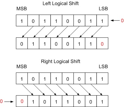
Fig. 1 Logical Shift by one bit
Arithmetic Shift
- A Left Arithmetic Shift of one position moves each bit to the left by one. The vacant least significant bit (LSB) is filled with zero and the most significant bit (MSB) is discarded. It is identical to Left Logical Shift.
- A Right Arithmetic Shift of one position moves each bit to the right by one. The least significant bit is discarded and the vacant MSB is filled with the value of the previous (now shifted one position to the right) MSB.
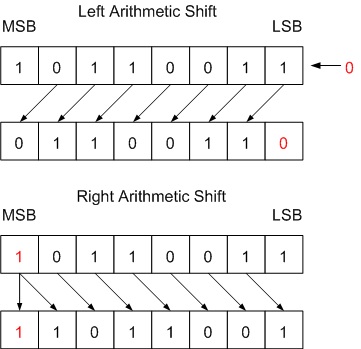
Fig. 1 Left and Right Arithmetic Shift by One Bit
Arithmetic Shift operations can be used for dividing or multiplying an integer variable.
- The shift operators provided in Verilog are:
|
Operator |
Description |
|
>> |
Right
shift |
|
<< |
Left
Shift |
|
>>> |
Arithmetic
Right Shift |
|
<<< |
Arithmetic
Left shift |
We will be able to gain a clear understanding
of how a shift operator works in Verilog from the below code:
module
shift_operators;
reg [3:0]
var1 = 4'b1000;
reg signed
[3:0] var2 = 4'b1000
initial
begin
//left
shift
$display("%b",
var1 << 1);
$display("%b",
$signed(var1) <<< 1); // Cast as signed
$display("%b",
var2 <<< 1); //
Declared as signed type
// Right Shift
$display("%b",
var1 >> 2);
$display("%b",
$signed(var1) >>> 2); // Cast as signed
$display("%b",
var2 >>> 2) ; //
Declared as signed type
end
endmodule
Simulation
log
0000
0000
0000
0010
1110
1110
Concatenation Operators
Concatenation
operators are used to join different bits of data into one. Concatenations are
expressed using the brace characters { }, with commas separating the
expressions within.
We will get a better
understanding of the working of the concatenation operator from the simulated
output of the code below.
module
concatenation_operator;
reg A;
reg[1:0] B,
C;
reg[2:0] D;
initial
begin
A = 1'b1;
B= 2'b00;
C = 2'b10;
D = 3'b110;
$display
("concatenation(B,C) = %b", {B,C});
// two 2 bits joined to form 4 bit number
$display
("concatenation(A,B,C,D,3'b001) = %b", {A,B,C,D,3'b001});
$display
("concatenation(A,B[0],C[1]) = %b", {A,B[0],C[1]});
end
endmodule
Simulation
log
concatenation(B,C)
= 0010
concatenation(A,B,C,D,3'b001)
= 10010110001
concatenation(A,B[0],C[1])
= 101
Replication operator
The replication
operator is used to replicate a group of bits n times. It takes the format
{n{m}}, where n indicates replication multiplier i.e., how many times m should
be repeated.
For example, in
{3{2’b01}} 3 is the repetition multiplier and 2’b01 is what will be replicated
3 times.
It is important to note that the repetition
multiplier must be a constant.
Look at the Verilog
code and simulated output below to see how the replication operator works.
module
replication_operator;
reg A;
reg[1:0] B,
C;
reg[2:0] D;
wire Y;
initial
begin
A = 1'b1;
B= 2'b00;
C = 2'b10;
D = 3'b110;
$display
("replicating A = %b", {4{A}});
$display
("replicating A and B = %b", {{4{A}},{2{B}}});
$display
("replicating A,B,C = %b", {{4{A}},{2{B}},{C}});
end
endmodule
Simulation
log
replicating
A = 1111
replicating
A and B = 11110000
replicating
A,B,C = 1111000010
example: Concatenation and Replication Operations in Verilog

Testbench File for Concatenation and Replication Operations in Verilog


Conditional Operator
The conditional
operator selects an expression for evaluation depending on the value of the
condition.
condition?true_expression:false_expression
If the condition is
evaluated as false (or zero value), then false_expression is evaluated and used
as a result of an entire expression.
For example
assign out =
enable?data1:data2;
The above statement
means that out will be assigned data1 if enable is true(1) or zero if enable is false(0).
Verilog makes use of
the conditional operator in order to build tri-state buffers and multiplexers.
Let’s see how the
conditional operator can be used practically.
module
conditional;
reg check = 1'b1;
wire out;
assign out
= check ? 1'b1 : 1'b0;
initial
begin
#1;
$display("OUTPUT:
%s", check ? "HI THERE" : "POTATO");
$display("Value
of out: %b", out);
$display("%h",
(10 > 5) ? 16'hABCD : 16'h1234);
$display("%s",
(1 == 1) ? "YES, ONE EQUALS ONE" : "HOW DID YOU GET HERE");
end
endmodule
Simulation log
OUTPUT: HI
THERE
Value of out: 1
abcd
YES, ONE
EQUALS ONE
Operator Precedence in Verilog
We have discussed the
different operators that we can use in Verilog. Is it possible to use multiple
operators in a single expression? Undoubtedly, yes. Then how do we choose
which operation to perform first?
That is when the
operator precedence table comes to play.
This table describes
the order in which the operators are executed.
|
Precedence |
Operators |
Operator Symbols |
|
Highest |
Unary Multiply Divide, Modulus |
+ – ! ~ * / % |
|
Add Subtract Shift |
+ – << >> |
|
|
Relational Equality |
< <= > >= == !== === !=== |
|
|
Reduction Logical |
& ~& ^ ^~ | ~| && || |
|
|
Lowest |
Conditional |
?: |
For example:
A && B || C
&& D
// same as (A && B)
|| (C&&D) expression in parenthesis evaluated first
But, it is better to
use brackets rather than depending entirely on the precedence of operators.
This will ensure the readability of the expression and correctness of the
result.
Tabular summary
So, we have gone
through all the operators that Verilog has provided. Let’s summarize the
operators that we have learned.
|
Operator
Type |
Operator
Symbol |
Operation performed |
Number of operands |
|
Arithmetic |
* |
Multiply |
Two |
|
/ |
Divide |
Two |
|
|
+ |
Add |
Two |
|
|
– |
Subtract |
Two |
|
|
% |
Modulus |
Two |
|
|
** |
Power(exponent) |
Two |
|
|
Logical |
! |
Logical negation |
One |
|
&& |
Logical and |
Two |
|
|
|| |
Logical or |
Two |
|
|
^ |
Logical xor |
Two |
|
|
Relational |
> |
Greater than |
Two |
|
< |
Less than |
Two |
|
|
>= |
Greater than or equal to |
Two |
|
|
<= |
Less than or equal to |
Two |
|
|
Equality |
== |
Equality |
Two |
|
!= |
Inequality |
Two |
|
|
=== |
Case equality |
Two |
|
|
!=== |
Case inequality |
Two |
|
|
Bit-wise |
~ |
Bit-wise negation |
One |
|
& |
Bit-wise and |
Two |
|
|
| |
Bit-wise or |
Two |
|
|
^ |
Bit-wise xor |
Two |
|
|
^~ |
Bit-wise xnor |
Two |
|
|
Reduction |
& |
Reduction and |
One |
|
~& |
Reduction nand |
One |
|
|
| |
Reduction or |
One |
|
|
~| |
Reduction nor |
One |
|
|
^ |
Reduction xor |
One |
|
|
~^ |
Reduction xnor |
One |
|
|
Shift |
>> |
Right shift |
Two |
|
<< |
Left shift |
Two |
|
|
>>> |
Arithmetic right shift |
Two |
|
|
<<< |
Arithmetic left shift |
Two |
|
|
Concatenation |
{} |
concatenation |
Any number |
|
Replication |
{{}} |
Replication |
Any number |
|
Conditional |
?: |
Conditional |
Three |
Here we will construct a primitive calculator to add, subtract, multiply, and divide two four-bit numbers on the Basys3 board. Input bits and the operation type is represented by switches on the board. Output bit values are represented by LEDs on the board, Verilog description of the calculator.

Enforcing Vivado to Use DSP Block in Arithmetic Operations in Verilog
👉back to main page


No comments:
Post a Comment